MicroLogix 1100 Selection Guide
The Allen-Bradley family of MicroLogix programmable controllers provides four levels of control with the MicroLogix 1500, MicroLogix 1400, MicroLogix 1200, and MicroLogix 1100 series of controllers. In general, MicroLogix controllers provide single-device control solutions to machine applications, with a mix of communication ports and I/O points embedded in the Programable Logix Controller (PLC) itself. Often, small control applications require just a single PLC base unit. But when additional communication or I/O options are required, the four types of MicroLogix controllers share expansion modules across the series. These expansion modules allow you to expand the capacity of your PLC platform for larger projects.
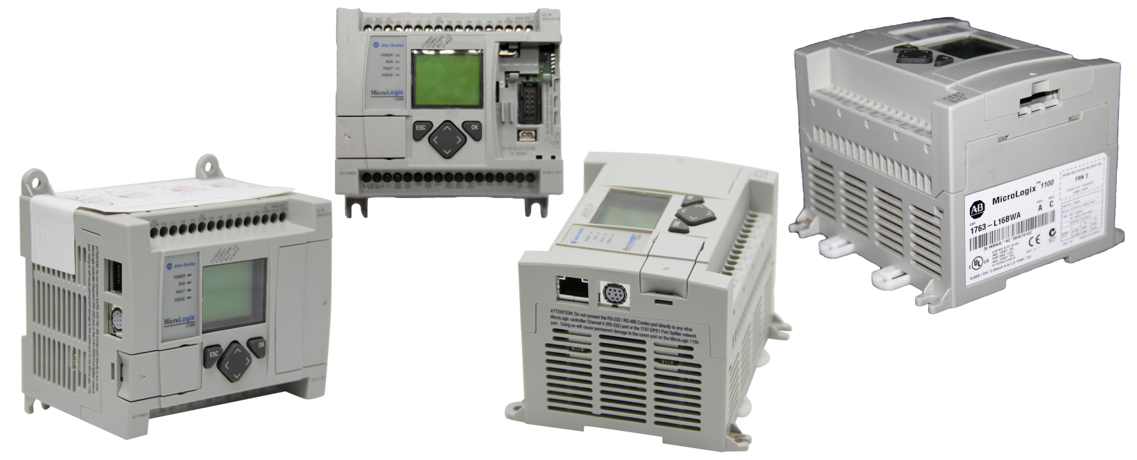
MicroLogix 1100 series is the newest member of the Allen-Bradley MicroLogix family. It enhances the functionality of MicroLogix controllers by providing advanced new features expanding the application coverage of these controllers at an affordable price. It is designed to broaden the application coverage area through Ethernet communications, embedded analog inputs, visualization capabilities, and true online editing. For example, all MicroLogix 1100 controllers have an Embedded LCD screen that allows users to monitor the controller’s data, modify that data if necessary and interact with the control program. The LCD screen also displays the status of the controller functions and embedded digital I/O.
Note, Allen Bradley makes use of Bulletin numbers to categorize each of its product lines. For instance, the MicroLogix 1100 series has a Bulletin number of 1763. This Bulletin number is in turn the prefix for all catalog numbers specific to the 1100 series, used when specifying and ordering different MicroLogix 1100 controller models. However, some components like expansion I/O modules are shared across the MicroLogix family, this makes the selection of compatible components for each series a little more complicated. For example, MicroLogix 1200 and 1100 share an add-on expansion I/O module with catalog number 1763-L16BBB.
Further on, you might find that the part number of the communication cable added to your MicroLogix 1100 is 1761-CBL-AM00, while the 1761 Bulletin number corresponds to the MicroLogix 1000 series. Also, MicroLogix 1100 controllers are compatible with an 8-point relay output module with a part number of 1792-OW8. Therefore, extra attention is needed when specifying the components and accessories of any MicroLogix 1100 controller before purchase, to ensure compatibility. This article will provide you with a selection checklist as a guide to specifying your own MicroLogix 1100 system.
Selection Criteria
The election of MicroLogix 1100 Controllers is based on available memory, I/O capabilities, added functionality, requirements for future expansion, compatible communication networks, programming instructions, and cabling requirements. Also, you must review your application considerations to determine the power and I/O specifications of the MicroLogix 1100 controller. There are several key features and factors you should consider whenever you’re selecting a MicroLogix 1100 controller, such as memory, I/O capabilities, expansion I/O modules, applications, communication options, and communication cables.
Memory Considerations
You must check the memory capacity of the MicroLogix 1100 controller you are considering because the memory size determines the range of applications that the selected controller can solve. Controllers within the MicroLogix 1100 series offer large size user memory of 8K, which is divided into 4k in user words data memory and 4k in user words program memory. Also, it has up to 128k bytes for data logging, as well as 64k bytes for recipe storage-which are subtracted from data logging storage. In terms of Memory User Data/User Program, the available MicroLogix 1100 controllers are categorized as follows: (i) Up to 1 KB (Kilobyte); (ii) Up to 6 KB; and (iii) Up to 8 KB (4 KB/ 4 KB).
In addition, ensure that the MicroLogix 1100 controller that you select has a memory module port in place. The memory module provides a backup that is removable for the User Data and User Program memory and acts as a means of transporting the user-defined programs between MicroLogix controllers. It also enables auto-recovery after a controller fault, removal/insertion under power, and special security/safety for critical applications, such as press controllers.
Required I/O Capabilities
Before selecting a MicroLogix 1100 controller, ensure that you review its power and I/O configurations. In that case, check the power supply and I/O specifications in detail to ensure that they satisfy your application requirements.
Each MicroLogix 1100 controller has two embedded analog inputs, 6 digital outputs, and 10 digital inputs. For small control applications, the embedded I/O on a single 1100 controller may represent all the required control. On the controller versions with DC inputs, they have a high-speed counter, and in the versions with DC outputs, there are two Pulse Train Outputs (PTO)/ Pulse Width Modulated (PWM) outputs. The PTO/PWM outputs enable a MicroLogix 1100 controller to support simple motion capabilities.
The MicroLogix 1100 series consists of 4 standard PLC models which have different catalog numbers, as shown in the information below.
- 1763-L16AWA: This controller has a supply voltage rating of 120/240 volts AC, ten (10) 120-volt AC digital inputs, two (2) 10-volt analog inputs, and six (6) individually isolated relay outputs.
- 1763-L16BWA: This controller has a supply voltage rating of 120/240 volts AC, six (6) 24-volt DC digital inputs, four (4) fast 24-volt DC inputs, two (2) 10-volt analog inputs, six (6) individually isolated relay outputs, and four (4) 20-kHz high-speed inputs.
- 1763-L16BBB: This controller has a supply voltage rating of 24 volts DC, six (6) 24-volt DC digital inputs, four (4) fast 240-volt DC inputs, two (2) 10-volt analog inputs, two (2) 24-volt DC isolated relay outputs, four (4) 24-volt DC FET outputs, two (2) 24-volt DC fast FET outputs, four (4) 20 kHz high-speed inputs, and two (2) 20 kHz high-speed outputs.
- 1763-L16DWD: This controller has a supply voltage rating of 12/24 volts DC, six (6) 12/24-volt DC digital inputs, four (4) fast 12/24-volt DC inputs, two (2) 10-volt analog inputs, six (6) individually isolated relay outputs, and four (4) 20 kHz high-speed inputs.
These models vary in power supply voltages, I/O types, and exceptional motion capabilities. The chassis enclosures between these models are physically the same, but the I/O assignments are different internally. Common to all the four models are advanced PID control, integrated communication options, an embedded LCD screen, and online editing functionality.
The online editing function allows you to monitor and modify the pre-existing Ladder Logic program, whenever the programming device is connected to the MicroLogix 1100 processor. Online editing functions include inserting, replacing, and deleting Ladder Logic rungs while the processor is online. This way, you can make changes to the program while it’s running, which makes fine-tuning of operating control systems highly possible, including PID loops. Thus, online editing not only reduces development time, but it helps in troubleshooting.
Note, that only one programming terminal can perform an online edit on the controller’s user program at a given time. Otherwise, when online editing starts, the MicroLogix 1100 rejects access from other programming devices.
Select Expansion I/O Modules
The MicroLogix 1100 I/O selections listed in the table above are all embedded into each of the controller’s chassis. But you can achieve additional I/O capacity using expansion modules regardless of the chosen I/O base unit. So, the selected controller should support additional digital, analog, thermocouple, and RTD (Resistance Temperature Detector) I/O modules to cater to any future expansion needs of your application.
MicroLogix 1100 controllers can be expanded using the same 1762 I/O modules as MicroLogix 1200 controllers. The 1762 expansion I/O platform provides superior control functionality in a small-sized, cost-effective package. A variety of these expansion modules can be added to the embedded I/O to complement and extend the application capabilities of the MicroLogix 1100 series, by optimizing the flexibility of I/O type and count. For example, a single MicroLogix 1100 controller can be expanded with up to four 1762 I/O modules.
Application Considerations
MicroLogix 1100 controllers are ideal for a wide variety of control applications. They are particularly well suited to meet the needs of SCADA RTU (Remote Terminal Unit) applications. As small portions of a more extensive control process can be decentralized to local MicroLogix 1100 programmable controllers and integrated through various communication protocols across a SCADA (Supervisory Control and Data Acquisition) array.
With even more memory for recipe storage and data logging than other MicroLogix controllers, the MicroLogix 1100 series provides a robust and cost-effective solution for remote monitoring, material handling, sub-system or small machine, remote interface control as well as for memory-intensive applications, but which require limited I/O such as batching and recipe automation.
For example, if you have a standard relay, start-stop type of control application; then the 1763-L16AWA Controller would be the best option. If you’re considering using instrumentation input devices for condition monitoring or online processes, such as through temperature or pressure sensors; you can get this functionality with any MicroLogix 1100 option, as all the four models within this series have two (2) 10V analog inputs onboard.
In addition, if your application entails complex process conditions that require high-speed counter inputs, then you can select either 1763-L16BWA, 1763-L16BBB, or 1763-L16DWD. The three controller models would work well in such applications, depending on the input voltage. On the other hand, if you’re considering adding an expansion analog output. You can select any MicroLogix 1100 model as the base unit and add an expansion output module with analog outputs, such as the 4-channel 1762-IF4 module.
Moreover, you can add a 1763-MM1 memory module, if your MicroLogix 1100 application requires additional security for onboard program backups. As previously stated, this memory module is entirely for removable backups, program auto-recovery, and transporting program copies between controllers. It does not provide additional system space to the already existing controller memory capacity, as perceived.
Select Additional Features
Check whether your application requires a MicroLogix 1100 controller with any of the following additional features:
- One (1) 40kHz embedded high-speed counter, for controllers with DC inputs.
- Two (2) 40kHz high-speed PTO/PWM outputs, for controllers with DC outputs.
- Two (2) embedded analog inputs, with a voltage rating ranging between 0-10 VDC, and a 10-bit resolution.
- An operator interface for input bit/integer and messages.
- 4K user words data memory and 4K user words program memory.
- Up to 64K bytes for recipe and 128K bytes for data logging.
If yes, then ensure that the controller you select has the required additional features.
Communication Options
When considering the communication options for your MicroLogix 1100 controller, ensure that you select a communication network that best meets your application needs, as well as the appropriate communication interface device if required.
Communication Networks
Each of the four models of MicroLogix 1100 controllers supports the following communication networks, from which you can choose.
- Integrated 10/100 Mbps EtherNet/IP port. This port supports peer-to-peer messaging, providing users with high-speed connectivity between MicroLogix 1100 controllers. Also, Ethernet communication allows users to access, monitor, and program the controllers from any location within the network coverage. In addition, direct EtherNet/IP connections via MicroLogix 1100 controllers support email communication and they provide web server capabilities.
- Channel 0 provides an isolated RS-232 port. Through the RS-232 serial protocol, MicroLogix 1100 controllers can support DF1 Half Duplex/ DF1 Full-Duplex Master and Slave, or ASCII messaging which provides dial-out capability, or DF1 Radio Modem useful for remote communication. The available data transmission speeds for these RS-232 communications include 600, 300, 4800, 1200, and 9600 bps (bits per second); 19.2 and 38.4 Kbps (Kilobits per second). Also, MicroLogix 1100 controllers support RTS/CTS (Request to Send/ Clear to Send) hardware handshake signals, which is a flow mechanism of the RS-232 standard.
- Through the RS-485 serial protocol, MicroLogix 1100 controllers support a direct interface to Modbus RTU and DH-485 Master/Slave networks without the need for an external electrical interface converter.
Note, MicroLogix 1100 controllers can also connect directly to Modbus RTU Master/Slave through the 1763-NC01 communication cable to Channel 0. You can also select Channel 0 isolated RS-485 or RS-485 Combo port through the chosen communication cables.
MicroLogix Communication Interface Modules
The information below provides a detailed description of the available communication interface modules which can be used with MicroLogix 1100 controllers.
- 1761-NET-AIC: This module is an AIC+ Advanced Interface Converter. This device lets you connect a MicroLogix 1100 controller DH-48. It also allows a MicroLogix 1100 controller to initiate or respond to communications from other MicroLogix controllers, programming devices, or operator interfaces through the Modbus RTU master/slave protocol.
- 1761-NET-DNI: This module is a DeviceNet Interface. It supports Pee-to-Peer Messaging between Allen-Bradley MicroLogix controllers. It allows you to connect MicroLogix 1100 controller or otherDF1 full-duplex devices to the DeviceNet network. This module allows a MicroLogix 1100 controller to function as a DeviceNet slave I/O node that provides 16 words of input/output data which can be exchanged with a DeviceNet scanner module (1769-SDN).
- 1761-NET-ENI: This module is an EtherNet/IP Interface. This device provides EtherNet/IP connectivity between MicroLogix 1100 controllers and other devices using the DF1 Full-Duplex protocol. It also allows for an easier connection from a MicroLogix 1100 controller to an existing or new Ethernet network to download/update programs. It supports email communication through SMTP (simple mail transport protocol) programs.
- 1761-NET-ENIW: This module is an EtherNet/IP Interface and is web-enabled. It adds web server capabilities to the MicroLogix 1100 controllers, allowing the display of 4 standard data web pages with 10 user-configurable web page links and with user-configurable data descriptions on the home page of the ENIW interface.
Note, that these MicroLogix communication interface devices can be panel mounted or mounted on a DIN rail. Also, whereas all other MicroLogix controllers do provide 24V DC power for the network interface modules, the MicroLogix 1100 and 1400 controllers don’t. Therefore, whenever you consider using 1761-NET-ENIW or 1761-NET-AIC or 1761-NET-ENI modules with either MicroLogix 1400 or 1100 controller, you should also provide 24V DC comms power externally.
Select Communication Cables
Communication cables are available in several connector styles and lengths. If you need to connect a MicroLogix 1100 controller with other devices, ensure that you review the port identification description to find the appropriate network cable from a selection chart.
Conclusion
With an integrated 10/10 EtherNet/IP port that provides peer-to-peer messaging and the online editing function, the MicroLogix 1100 series adds greater connectivity and wider application coverage to the MicroLogix family. Also, with the next generation LCD screens embedded on MicroLogix 1100 controllers, users can view controller status, simpler operator messages, and I/O status; manipulate bit and integer inputs, and use the digital trim pot functionality. These features make the MicroLogix 1100 series stand out as the best option for a variety of industrial applications requiring compact controllers.
As a reminder, Allen-Bradley MicroLogix 1100 controllers have a Bulletin number of 1763 but they’re compatible with expansion I/O modules under Bulletin 1762, the expansion memory module with a Bulletin 1763, communication interface devices under Bulletin 1761, and communication cables under Bulletin 1761.
In addition, the functionalities, programming instructions, and communication interface types of MicroLogix 1100 controllers are all standardized across all the four available models. Hence, the selection criteria for choosing an 1100 controller model are essentially around the power supply voltages, I/O types, and count. Of the two, I/O selection is the key element warranting the most attention. We hope this selection guide will be valuable in comprehending your MicroLogix 1100 selection options.