100-D Contactor Selection Guide
A contactor is an electrical switching device. It is part of the relay family but it is used for applications in which high currents are involved. Contactors are highly versatile and are typically used to switch motors, lighting circuits, and capacitors (for power factor correction). As the name indicates, a contactor has similar functionalities to an ordinary on-off switch, since it is also used to break or make contacts in an electrical circuit.
A contactor consists of a set of power contacts, an electromagnet, and a spring housed in an enclosure. It is different from standard switches in that it has an electromagnet that holds the power contacts when energized. In addition, some contactors are fitted with built-in economizers to reduce power consumption within their coils. A contactor can function as part of a power control device or as part of a motor starter or on its own.
Working Principle of Contactors
The basic principle of operation of contactors is similar to that of electromechanical relays. The difference is that contactors are specifically designed to carry much more current than standard relays, and thus, they connect to high-current load devices. For instance, standard relays cannot be used to switch circuits whose current rating exceeds 20A (amperes), but contactors are available with up to a 12500-ampere rating. Contactors also feature high coil voltages, unlike other relays. It is possible to control contactors remotely when used in large-scale circuit control applications. However, contactors can only make or break contacts in an electrical power circuit when excited. They do not provide short circuit protection.
So, how does a contactor switch a high-current electrical circuit on or off? As previously mentioned, contactors incorporate spring-loaded power contacts and an electromagnet. Whenever an electric current passes through the contactor, the electromagnetic coil gets energized and produces an electromagnetic field. The generated electromagnetic field attracts the armature, thereby closing the gap between the contacts, hence switching on the electrical power circuit.
For contactors equipped with split electromagnets, the generated field attracts the movable half of the electromagnet towards the fixed electromagnet. This action causes the contacts to close, switching on the circuit. As long as the electromagnet remains excited, the contacts will remain closed and the power circuit will be on. However, when the electromagnetic coil is de-energized, the movable power contact will be pushed back to its normal position by spring action.
Note that the contacts are spring-loaded so that they can open and close very rapidly which assists with arc suppression. This ensures that the contactor is capable of interrupting high currents with minimal damage over a longer service life. However, movable contacts are likely to bounce as they rapidly make contact with the fixed contacts. Bifurcated or twin contacts can be used to improve contactor reliability and avoid the bouncing of movable contacts.
To provide excitation power to the electromagnetic coil of the contactor, either AC or DC, or even a universal voltage, can be used. Contactors with universal coils can operate on DC, as well as AC, voltages. During switching operations, the coil drains a small amount of power. Therefore, it is recommended that you include economizer circuits to reduce the power consumed by the contactor coil while switching.
AC-operated contactors operated have shading coils integrated with their AC coils. The shading coils delay demagnetization of the electromagnetic core, this prevents chattering. Otherwise, the AC coils could chatter every time the alternating current passes zero. Contactors with DC coils do not require shading coils as the magnetic flux produced is constant.
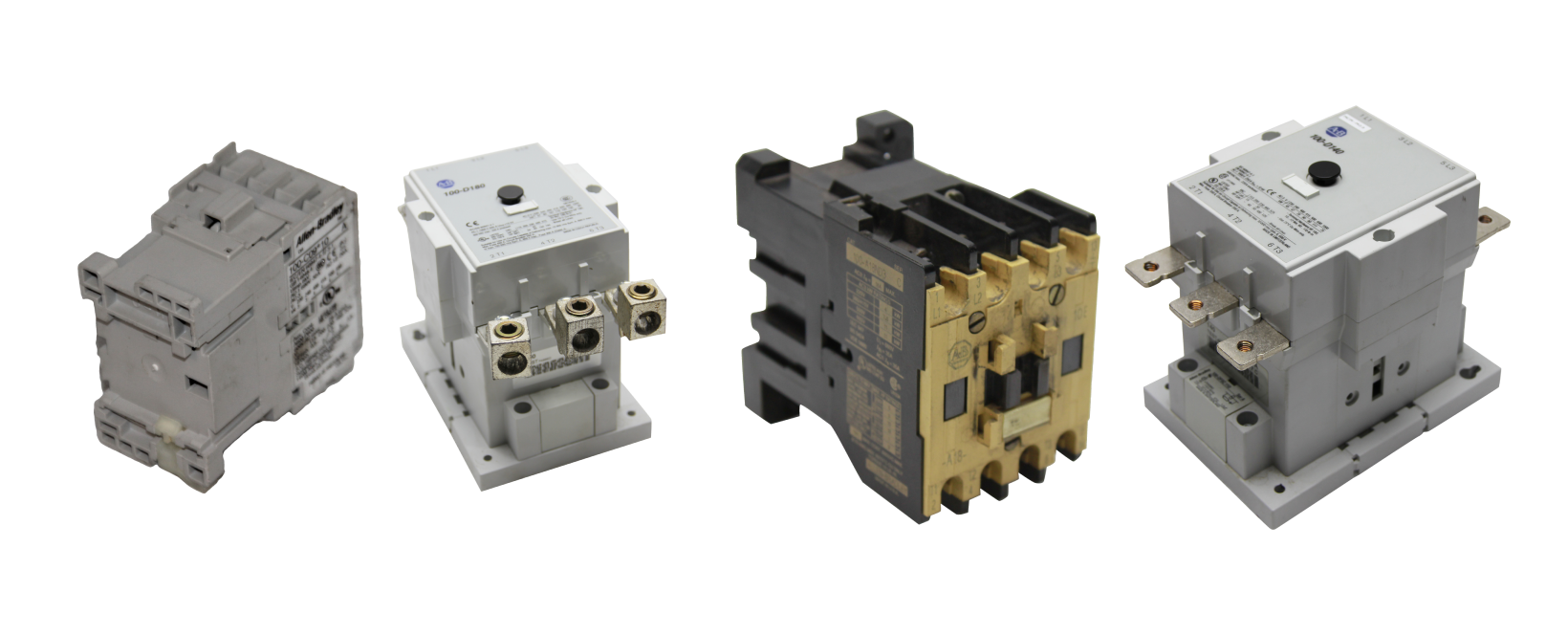
The Allen-Bradley 100-D Contactor Series
The compact yet powerful 100-D series of IEC contactors is manufactured by Allen-Bradley/Rockwell Automation. They are versatile and exceptionally performing contactors, designed with high switching power to handle high-level currents of modern motors and other electrical loads. They have two separate power connections per pole which greatly enhances their connection reliability and ease-of wiring, saving you valuable time. Also, 100-D contactors are considered highly efficient as their coils have low power consumption. In addition, their smaller frame design saves lots of panel space. Most importantly, 100-D contactors are RoHS (Restriction of Hazardous Substances Directive) compliant as they are made of environmentally friendly materials, giving you a better choice for your work personnel and the planet at large.
How to Choose the Right 100-D Contactor
Even though the contactor is probably one of the most commonly used components in industrial or motor control applications, selecting the correct one requires you to provide detailed application information. Regarding 100-D contactors, you have to first specify the type of load you need the contactor to handle based on IEC utilization categories.
Application-based on IEC Utilization Category
You must characterize the application of the contactor you’re planning to purchase based on the type of load (IEC utilization categories - IEC 60947). Electrical loads are categorized into various AC ratings (AC-1, AC-2, AC-23…etc). The higher the AC Rating, the more inductive the electrical load becomes. In case you are not sure of the specific load category, a full description of the nature of the electrical load for your particular application is required. There are three main applications of 100-D contactors which include:
-
Motor Starters: 100-D contactors can be used in motor starter circuits with either Star Delta or Direct-on-line (DOL) configurations. In these circuits, they are used for switching operations along with short circuit protection devices and overload relays.
-
Switching Capacitor Banks: In capacitor banks, 100-D contactors can be used to switch capacitors on or off, based on the specified reactive power requirements. The contactors selected for capacitor switching should be able to control the high transient currents that are formed while switching. In such applications, additional resistors should be provided to reduce inrush currents during switching operations.
-
Lighting Circuits control: 100-D contactors can be used in timer-controlled lighting circuits to switch residential, commercial, and street lights. In this application, the 100-D contactors used should have two coils where one of the coils will be used for opening the contacts and the other for closing the contacts. When excited, the closing coil closes the contacts, cutting off the current supply to the coil. Mechanical means are used to hold the contacts closed. The opening coil will then be used to open the contacts.
After identifying the specific type of load to be handled by the contactor you’re considering, based on IEC-utilization categories, the next step will be to fully specify the following 3 key elements to select the right 100-D contactor for your application.
Coil Selection
The coil is a part of the electromagnet used to energize the contactor, for switching the main poles on and off. When choosing the contactor coil, you have to consider a few factors:
-
The type of operating voltage: 100-D Contactors can be AC-operated, DC-operated, or Universal. Universal contactor coils can operate on either DC or AC voltages.
-
The voltage of the coil: The coil voltage is often different from the voltage of the main contacts. AC-operated 100-D contactors with Conventional Coils are available with the following AC voltages: 24V, 48V, 100V, 110V, 120V, 200V, 208V, 220 to 230V, 240V, 277V, 380 to 400V, 415V, 440V, 480V, 500V, 550V, and 600 V. For Electronic Coils with an EI Interface, the available AC voltages within the 100-D contactor series include: 24V, 42 to 64V, 100V, 110 to 130V, 200V, 208 to 277V, 200 to 220V, 230 to 250V, 380 to 415V, 380 to 500V, 440 to 480V, and 500V. Additionally, you have to select the correct supply frequency for the AC coils. 100-D contactors provide a frequency of 50/60 Hz for the AC coils.
If you prefer a DC-operated 100-D contactor, the available DC voltages for conventional coils include 24V, 48V, 110V, 125V, and 220V. For Electronic Coils with an EI interface, the 100-D contactors provide the following DC voltages: 24V, 48 to 72V, 110 to 130V, and 200 to 255V. Also, for the DC coils, you must specify if a low power consumption option is required.
Main Contacts Selection
Also referred to as the main poles, main contacts form a part of the contactor that carries current. When selecting the main pole element of your contactor, consider the required number in either normally open (N.O.) and/or normally closed (N.C.) contacts format. For motor applications, be sure to specify whether you need a 100-D contactor with non-reversing or a reversing functionality. A non-reversing contactor is used to just turn the motor on and off, while a reversing contactor is used when you need to reverse the rotation of your motor.
Also, depending on your application, determine whether you need main poles with AC or DC voltage ratings. In addition, specify the required rating of the main contacts switching current. 100-D contactors are available in a wide range of current ratings, which could range between 9 amperes to 2650 amperes.
Lastly, when selecting the main poles, consider the required IEC utilization category. 100-D contactor electrical loads/duty are categorized as either AC-1, AC-3…etc., DC-1 to DC-21. This categorization is based on the number of start/stop operating cycles and the type of resistive or inductive load. In case you are not sure of the specific load category, familiarize yourself with the full description of the nature of the given electrical load (i.e., resistive heating, lighting…etc.), breaking current, making current, as well as the continuous flow of current through the contacts.
Auxiliary Contacts Selection
Auxiliary contacts are used for signaling and control circuit applications. Specify the required quantity of either normally open (N.O.) and/or normally closed (N.C.) contacts. Note that the current rating of the auxiliary contacts may not be the same as that of the main poles. However, if the auxiliary contacts are not used in standard signaling applications which require low power, then you can use the requirements of main poles to specify them. In addition, some contactor models provide time-delayed auxiliary contacts. There are a variety of auxiliary contacts available with the 100-D contactor series, which include:
- Side-mounted auxiliary contacts, without IEC sequence terminal designations. In this category, the standard contacts are rated at 17 volts at 10 milliamperes, while Bifurcated contacts for low signals down are rated at 5 volts at 2 milliamperes.
- Electronic-compatible auxiliary contacts, which are well-suited for switching operations of low-power control circuits. This category has IEC sequence terminal designations. The ratings of the contacts in this category include AC-15, DC-13, 3 to 125V, 1 mA to 100 mA, and AC-12, 250V, 0.1 A. Electronic-compatible auxiliary contacts similar to category 2, but without IEC sequence terminal designations, are also available.
Selection Criteria for 100-D Contactor Accessories
Surge Suppressor Modules
Check if your application requires a 100-D contactor with a coil surge suppressor, to limit the surge voltage whenever the coil circuits are interrupted. All electronic coil and conventional DC-coil 100-D contactors are supplied with integrated Suppressor modules as a standard feature. There are different types of suppressor modules available with the 100-D contactor series. Therefore, select the module that meets your voltage rating and application requirements. The available modules include:
- RC (Remote Control) Suppressor Module (AC controlled) for conventional coil 100-D contactors. The available ratings for this module are 21V to 48V at 50 Hz, 24V to 55V at 60 Hz, 380V to 550V at 50 Hz; and 440V to 600V at 60 Hz.
- Varistor Suppressor Module for conventional coil 100-D contactors whose voltage ratings range between 55V AC and 600V AC
- Varistor Suppressor Module for 100-D contactors with an electronic coil. The available voltage ratings include: 208V to 277V AC rated as overvoltage category IV (IEC 947 for 100-D... -EI), such as lightning protection requirements, and 380V to 500V AC for surge pulses greater than 1 kilovolt.
Control System
Be sure to check the type of control system that is compatible with your selected 100-D contactor. For example, the 100-D110EA00 and 100-D110EZD11 electronic coil contactors come with an integrated PLC interface. Other contactors, such as the 100-D300ED11, are compatible with both DC and AC PLC interfaces. There are also some contactors in the 100-D series which are fitted with an Allen-Bradley Modular Control System (MCS).
The MCS allows users to design and construct flexible and adaptable systems using a wide range of accessories to cater to a variety of needs. Therefore, if some of the key factors for your contactor application are ease of assembly, modern design, reduced enclosure volume, weight savings, ease of installation, and modification, be sure to select a 100-D contactor with a Modular Control System.
Standards Compliance and Certifications
Your selected 100-D Contactor should comply with the following standards: CSA C22.2 No. 14, IEC 60947-4-1, UL 508, and IEC 60947 Type 2 Coordination.
Also, check that the chosen 100-D Contactor has the following certifications: CE Marked, c-UL-us Listed (File No. E 41850, Guide NLDX, NLDX7), and CCC (115A to 180A for conventional coil contactors and 140A to 420A for electric coil contactors).
Contact Configurations
The 100-D series provides contactors with a wide range of contact configurations including:
- Reversing: Input Connection with Wye-Delta: Main-Delta connection.
- Reversing: Output Connection with Wye-Delta: Delta-Wye connection.
- Delta-Wye connection, if 100-D115…100-D180 contactors are used as a Wye contactor.
- Wye-Delta: Neutral bridge for 100-D630… 100-D860 contactors. 100-D contactors using 100-DL lug kits require Power Wiring Kits.
Connecting Components
Be sure to check the connecting components that are compatible with your selected contactor. There are a variety of connecting components available with the 100-D contactor series, which include:
- Terminal Lugs: There are two different types of terminal lugs available for use with the 100-D contactors. These include a set of two (2) terminal lugs rated as Protection class IP2X based on IEC 60529 and DIN 40 050, as well as a set of three (3) terminal lugs (UL/CSA) with a copper frame. Check which of the two is compatible with your chosen contactor. Also, it is recommended to check if your contactor application requires a control circuit terminal.
- Terminal Shield: The Allen-Bradley 100-D contactor series is available with a set of two (2) terminal shields, rated as Protection class IP10 according to IEC 60529 and DIN 40 050. They can be used for two-speed, reversing, wye-delta/star-delta, and direct-on-line (DOL) assemblies.
- Terminal Covers: Different types of contactors within the 100-D family can be used with different terminal covers. The available terminal covers within this series include a Line-side panel relay and reversing cover, a Reversing Starter/relay cover, and a Direct-on-line (DOL) Starter/relay cover.
- Mounting Plate: Selecting the mounting plate that will handle your contacts assembly is very important. The available plates for mounting the 100-D contactors include Galvanized steel mounting plates for starter combinations, as well as mounting changeover or two-speed switches.
- Interlocks: 100-D contactors can be used with either a Mechanical Only interlock or a Dual Electrical/Mechanical interlock. It is recommended to check which of the two is compatible with your selected contactor.
Environmental and Design Considerations
Check the specified ranges of environmental factors, such as humidity, ambient temperature, etc., to ensure that your selected 100-D contactor will function properly within the operating conditions provided in your facility. Also, see if your contactor requires any ancillary parts such as mechanical interlocks, motor protection circuit breakers, electronic timers, thermal overload relays, or busbars. If any of these parts is required, select the one that is compatible with your chosen 100-D contactor.
Take into account the total number of hours you would require the contactor to operate and if latching operation is required. Lastly, identify the specific design requirements for the contactor that will best suit your application. 100-D contactors are available in modular or stand-alone designs. Also, will the contactor require an enclosure like an enclosed motor starter?
Conclusion
The Allen-Bradley 100-D series, along with a wide range of accessories such as auxiliary contact blocks, surge suppressor modules, electrical and/or mechanical interlocks, integrated PLC controllers, Modular Control System (MCS), electronic overload relays, reversing power wiring kits, etc., provides the most flexible and compact contactors available. They are indispensable devices in most electrical circuit control applications. Although, as with every electrical device, you must find the right 100-D contactor that meets your application needs. This article provides you with detailed guidelines on how to choose the correct key elements and accessories for your selected 100-D contactor, based on your specific application.