MicroLogix 1400 Selection Guide
Allen-Bradley MicroLogix 1400 is a PLC family from Rockwell Automation that complements the existing MicroLogix series of small Programmable Logic Controllers (PLCs). It offers a great mix of high-speed I/O, a variety of communication protocols, embedded analog inputs, modular expandability, and a broadened application coverage.
MicroLogix 1400 controllers combine the features you would need from the MicroLogix 1100 series, such as Online Editing, EtherNet/IP, and built-in LCD, plus they provide you with upgraded features including faster High-Speed Counter (HSC)/ Pulse Train Output (PTO), enhanced network capabilities and higher I/O count. Thus, you can take advantage of the embedded LCD with backlighting to set up Ethernet network configurations, display OEM (Original Equipment Manufacturer) logos during startup, display user configurable floating points values, and read or write any integer and binary elements in the data table.
The enhanced features of MicroLogix 1400, such as batch recipe storage and high-speed outputs, allow for more complex levels of industrial automation, pushing beyond the limits of what is considered single-machine control. As a result, MicroLogix 1400 are commonly used in industrial environments to handle multi-axis machine motion, central ingredient distribution, multi-batch systems, and system control of small pilot plants, despite their size. Overall, the MicroLogix 1400 series is extremely powerful and robust for its size and cost.
Naturally, the memory capacity, I/O type, and count, as well as the programming instructions used will limit what applications a MicroLogix 1400 can handle. For that reason, there are several factors you’ll need to consider before immediately selecting any MicroLogix 1400 controller. This article will guide you in specifying the right features of a MicroLogix 1400 controller, to meet your application requirements.
Selection Criteria
When selecting a MicroLogix 1400 controller you should precisely review its features, including Memory capacity, I/O type and count, Power specifications, Communication options, Programming Instructions, and the required Accessories. Also, consider the need for future expansion, networked communication, and online editing.
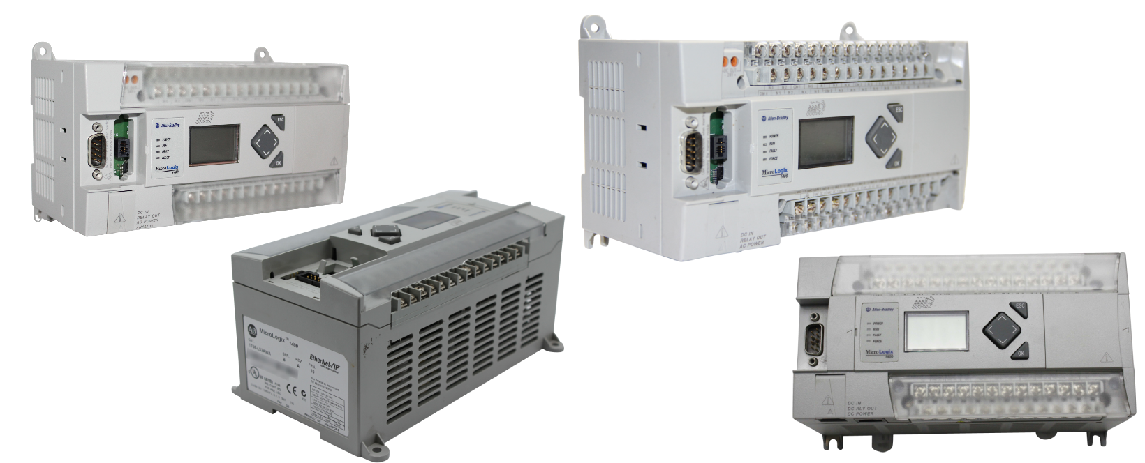
Note, that the Allen-Bradley series of MicroLogix 1400 controllers is identified under Bulletin 1766. This Bulletin is important when specifying the components of any MicroLogix 1400 controller, as each catalog number of every component available within the series is preceded by the applicable bulletin number.
Also, if you compare the bulletin numbers of all Allen-Bradley MicroLogix controllers (MicroLogix 1000-Bulletin 1761; MicroLogix 1100-Bulletin 1763; MicroLogix 1200- Bulletin 1762; MicroLogix 1400-Bulletin 1766; MicroLogix 1500- Bulletin 1764), you’ll notice that MicroLogix 1400 series has the highest bulletin number making it the latest product developed in the MicroLogix family. For this reason, the most advanced features of the MicroLogix controllers are found in the MicroLogix 1400 family.
Outlined below is a detailed guide on how to specify the various components of MicroLogix 1400 controllers.
Memory Requirements
All MicroLogix 1400 controllers have the following memory capabilities:
- 10 kb (kilobytes) word user-configurable Program memory
- 10 kb word user-configurable Data memory
- Up to 128 kb for Data Logging (without Recipe) and 64 kb for Recipe Storage (after subtracting Data Logging)
With large user data and user program memory, MicroLogix 1400 controllers can solve a variety of applications. Moreover, event-triggered or time-based data logging capability enables the MicroLogix 1400 controller to store data records with an optional time stamp in the separate 128 KB memory space for later analysis. A good example is trends and I/O status records during an alarm condition. On the other hand, the 64 KB Recipe Storage which is deducted from Data Logging memory, is accessible through the user-defined Ladder Logic program. It allows faster and easier batch changes of program data for counters, timers, and other data types.
Select MicroLogix 1400 I/O
From the information discussed above, we see that all controllers in the MicroLogix 1400 family are standardized in terms of memory and performance specifications. The main variation comes in the form of power specifications and I/O options. For this reason, your application requirements will be the primary differentiating factor between the 1400 controller models in terms of I/O options.
The information below specifies the six different controller models available in the MicroLogix 1400 series and their I/O configurations.
- 1766-L32BWA: This controller has a power line voltage rated at 120/240 volts AC. It has twelve (12) fast 24-volt DC inputs, eight (8) normal 24-volt DC inputs, and twelve (12) relay outputs. It has a power supply voltage rating of 100 to 240 volts AC at 47 to 63 hertz. It also has a power consumption rating of 120 volt-amperes. The maximum power supply inrush current at 120 volts AC is 25 amperes for 8 milliseconds and 40 amperes for 4 milliseconds at 240 volts AC.
- 1766-L32AWA: This controller has a power line voltage rated at 120/240 volts AC. It has twenty (20) 120-volt AC inputs and twelve (12) relay outputs. This device has a power supply voltage rating of 100 to 240 volts AC at 47 to 63 hertz. /It has a power consumption rating of 100 volt-amperes, along with a maximum power supply inrush current of 25 amperes for 8 milliseconds at 120 volts AC and 40 amperes for 4 milliseconds at 240 volts AC.
- 1766-L32BXB: This controller has a power line voltage rated at 24 volts DC. It has twelve (12) fast 24-volt DC inputs, eight (8) normal 24-volt DC inputs, six (6) relay outputs, three (3) fast 24-volt DC outputs, and three (3) normal 24-volt DC outputs. This device has a power supply voltage rating of 24 volts DC with a power consumption rating of 7,5 to 53 watts. The maximum power supply inrush current is 15 amperes for 20 milliseconds at 24 volts DC.
- 1766-L32BWAA: This controller has a power line voltage rated at 120/240 volts AC. It has twelve (12) fast 24-volt DC inputs, eight (8) normal 24-volt DC inputs, twelve (12) relay outputs, four (4) voltage inputs, and two (2) voltage outputs. The power supply voltage is rated at 100 to 240 volts AC at 47 to 63 hertz. It has a power consumption rating of 120 volt-amperes, as well as a maximum power supply inrush current of 25 amperes for 8 milliseconds at 120 volts AC and 40 amperes for 4 milliseconds at 240 volts AC.
- 1766-L32AWAA: This controller has a power line voltage rated at 120/240 volts AC. It has twenty (20) 120-volt AC inputs, twelve (12) relay outputs, four (4) voltage inputs, and two (2) voltage outputs. This controller has a power supply voltage rating of 100 to 240 volts AC at 47 to 63 hertz with a power consumption rating of 100 volt-amperes. It has a maximum power supply inrush current of 25 amperes for 8 milliseconds at 120 volts AC and 40 amperes for 4 milliseconds at 240 volts AC.
- 1766-L32BXBA: This controller has a power line voltage of 24 volts DC. It has twelve (12) fast 24-volt AC inputs, eight (8) normal 24-volt DC inputs, six (6) relay outputs, three (3) fast 24-volt DC outputs, three (3) normal 24-volt DC outputs, four (4) voltage inputs, and two (2) voltage outputs. This controller has a power supply voltage rated at 24 volts DC with a power consumption rating of .5 to 53 watts. The maximum power supply inrush current is rated at 15 amperes for 20 milliseconds at 24 volts DC.
So, whenever you’re selecting the MicroLogix 1400 I/O options, you’ll first decide on the controller model that has your required I/O type and count, then pick the power supply that meets the power specifications of your selected controller model and I/O voltages. Note, that the MicroLogix 1400 base units house the embedded inputs, outputs, communication ports, and the power supply.
Therefore, to select a specific MicroLogix 1400 controller catalog number you should first review its power and I/O configurations based on your application considerations. For example, you can select the 1766-L32AWA MicroLogix 1400 model, if your application is a standard relay control, stop-start type.
Consider the 1766-L32AWAA model for adding instrument inputs in condition monitoring or online process applications, such as through a temperature or pressure sensor. Furthermore, the 1766-L32BWAA model is ideal for applications requiring monitoring of more complex process conditions, like a system with a high-speed flow meter input and multiple modulating control valve outputs.
Select 1762 Expansion I/O Modules
If your MicroLogix 1400 I/O count is more than the base chassis count, then you can add additional Expansion I/O with Bulletin 1762. The base unit of the selected MicroLogix 1400 controller should provide the interface to expansion I/O modules when required by an application.
The 1762 Expansion I/O modules provided by Allen-Bradley for use with any MicroLogix 1400 controller include:
- Digital 1762 Expansion I/O: The modules available within this category include the 8-Point 120V AC Input Module (1762-IA8), the 8-Point Sink/Source 24V DC Input Module (1762-IQ8), the 16-Point Sink/Source 24V DC Input Module (1762-IQ16), the 32-Point Sink/Source 24V DC Input Module (1762-IQ32T). the 8-Point 120/240V AC Triac Output Module (1762-OA8), the 8-Point Sourcing 24V DC Output Module (1762-OB8), the 16-Point Sourcing 24V DC Output Module (1762-OB16), the 32-Point Sourcing 24V DC Output Module (1762-OB32T), the 32-Point Sinking 24V DC Output Module (1762-OV32T), the 8-Point AC/DC Relay Output Module (1762-OW8), 16-Point AC/DC Relay Output Module (1762-OW16), the 6-Point Isolated AC/DC Relay Output Module (1762-OX6I), and the 8-Point Sink/Source 24V DC Input and 6-Point AC/DC Relay Output Module (1762-IQ8OW6).
- Analog 1762 Expansion I/O: There are three modules in this category, which include the 4-Channel Voltage/Current Analog Input Module (1762-IF4), the 4-Channel Voltage/Current Analog Output Module (1762-OF4), and the Combination 2-Channel Input 2-Channel Output Voltage/Current Analog Module (1762-IF2OF2).
- Temperature 1762 Expansion I/O: These include the 4-Channel RTD/Resistance Input Module (1762-IR4), as well as the 4-Channel Thermocouple/mV Input Module (1762-IT4).
Note, that up to seven 1762 Expansion I/O modules, in any combination, can be added to a MicroLogix 1400 controller. These modules can either be panel mounted or connected to a DIN rail.
Select Communication Options
Select the appropriate communication network based on the requirements of your application. The MicroLogix 1400 controllers are fitted with three embedded communication ports which provide enhanced communication capabilities.
These ports can be used for the following types of communication:
-
Isolated RS-232/485 port (Channel 0): This port is used to connect MicroLogix 1400 controllers to:
- Personal computers, operator interfaces…etc., using DF1 Full-Duplex point-to-point.
- DH-485 network, DF1 Radio Modem network, DF1 half-duplex network as an RTU Master/Slave
- Modbus network as an RTU Master/Slave
- ASCII network
- DNP3 network as a Slave
- Ethernet networks using an Ethernet Interface module (either 1761-NET-ENI, or 1761-NET-ENIW)
-
RJ45 Ethernet port (Channel 1): In MicroLogix 1400 controllers, this port supports:
- 10 Mbps or 100 Mbps Ethernet/IP peer-to-peer messaging
- CIP explicit messaging (message exchange) only
- DNP3 over IP
- Modbus TCP/IP protocol
-
Non-isolated RS-232C port (Channel 2): It is used to connect MicroLogix 1400 controllers to:
- DF1 full‐duplex, DF1 radio modem, DF1 half‐duplex Master/Slave
- DH‐485 using an Advanced Interface Converter (1761‐NET‐AIC) for networking; external power is also required
- Modbus RTU master and RTU slave, using 1761‐NET‐AIC interface module; this connection requires external power for networking
- DNP3 Slave protocol
- ASCII Network
The MicroLogix 1400 controllers support EtherNet/IP™ communications and CIP (Common Industrial Protocol) Explicit messaging through the Ethernet communication port-Channel 1. However, these controllers cannot be used for real-time I/O messaging (CIP implicit messaging). The MicroLogix 1400 also has an embedded web server that allows viewing of module information, the data table, diagnostic information, and TCP/IP configuration.
Select MicroLogix Communication Interface Devices
Note, if your application requires a communication interface device, be sure to select the interface module that is compatible with your main communication network. For example, you would require an Advanced Interface Converter (AIC+) with catalog number 1761-NET-AIC, to connect your Personal Computer (PC) to a DH-485 network or other products in the MicroLogix Family.
But you can directly connect MicroLogix 1400 controllers to the RS-485 network via Channel 0, using DH-485, Modbus RTU Master/Slave, DF1 Half-Duplex Master/
Slave, or DNP3 Slave protocols. In that case, you won’t require an external optical isolator like the 1761-NET-AIC, since Channel 0 is already isolated within the MicroLogix 1400 controller. Therefore, the use of MicroLogix Network Interface Devices is specific to the application at hand.
Select Communication Cables
When selecting the communication cables, identify the communication ports of the device you need to connect to and find an appropriate cable in the provided selection chart. The communication cables specified for use with MicroLogix 1400 controllers include the 1761-CBL-AM00 series C or higher, the 1761-CBL0AP00 series C or higher, 1761-CBL-PM02 series C or higher, and the 1761-CBL-HM02 series C or higher. Note, that the communication cables listed prior are required for applications rated Class I Div.2
Select MicroLogix 1400 Accessories
The MicroLogix 1400 series has two types of accessories: the Memory Module and the Real-Time Clock. Hence, any controller you select within this series should have a built-in real-time clock, which provides a reference for all applications that require time-based control.
Also, all MicroLogix 1400 controllers are purchased with an onboard memory module cover port. Then, you can purchase the 1766-MM1 memory module as an accessory and install it. The memory module provides a removable and optional backup for your user data and program memory. It is optional because the program and data memory embedded in your MicroLogix 1400 are non-volatile, so it will still be retained even in the event of a power loss. The memory module thus provides an additional memory backup that can be stored separately. It can also be used to transport the user programs between MicroLogix controllers.
Conclusion
In conclusion, a typical MicroLogix 1400 controller contains a processor, input and output circuits, a power supply, and three in-built communication ports (an Ethernet Port-Channel 1, an isolated combination RS-232/RS-485 port-Channel 0, and a non-isolated RS-232C port- Channel 2). The embedded Ethernet port supports Web Server, E-mail capabilities, and Ethernet/IP peer-to-peer messaging. Communication Channel 0 and Channel 2 are serial ports that support DH485/DF1/DNP3/ Modbus RTU/ASCII protocols.
Each MicroLogix 1400 controller supports the following features: 10KB word user program memory, 10KB word user data memory, a maximum of 128k bytes for data logging, and 64k bytes for recipe storage, True online editing, Onboard LCD screen, 6 analog I/O points (4 analog inputs and 2 analog outputs), and 32 digital I/O points (20 digital inputs, 12 discrete outputs). Also, you can expand a MicroLogix 1400 controller with up to seven 1762 Expansion I/O modules, for a maximum of 256 digital I/O points.
The target applications for MicroLogix 1400 controllers include General Industrial Machinery (Packaging, Assembly, Material Handling, …etc.), Clutch/ Brake Control, Food & Beverage, Pharmaceutical, SCADA systems (in Oil & Gas, Electric Power, and Water/Waste Water), as well as in Commercial Machinery (Industrial Washers, Dryers, and Vending).